
8DI/8RO 16DI/16RO 8CH 16CH Relay RS485 Modbus RTU

- Weight:
- 0.16 KGS


Description
First, the product overview
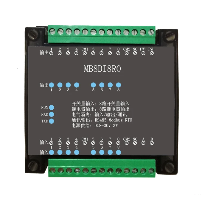
The MBSL8DI8RO module is an 8-channel digital isolated input and 8-channel digital relay isolated output module, which is output through an isolated RS485 interface. The module adopts standard Modbus RTU communication, which can directly adapt to various PC configuration software, PLC, DCS and so on. The module power supply and RS485 communication electrical signals are isolated from each other, effectively suppressing various types of series mode and common mode interference, and also ensuring stable and reliable operation of the module.
1, using RS485 MODBUS RTU standard communication, can be connected with the host computer configuration software, PLC, industrial touch screen, etc., with communication status indicator
2. Industrial grade standards: electrical signals such as signal control, power supply, and RS485 communication are isolated from each other.
3. The communication circuit adopts lightning protection, anti-interference design and power polarity protection.
4, RS485 communication signal output interface uses overvoltage and overcurrent double protection.
5, can be widely used in industrial field equipment signal acquisition and control.
6. Output network protection: When the slave station detects that the master station has not sent data for more than the set time, it automatically resets the output to protect the field equipment. Default no network protection function, can be selected by setting
7. The communication format can be set by software.
Second, the main technical indicators
|
Project |
Technical indicators |
|
Signal input/output |
1, input channel: 8 digital inputs 2, output channel: 8 relay output 3, load capacity: resistive load 5A / channel |
|
Communication output |
1. Communication protocol: MODBUS-RTU 2. Interface type: isolated RS485 communication, output interface with overvoltage and overcurrent double protection 3. Baud rate: 4800bps, 9600bps, 19200bps, 38400bps, 57600bps 4. Check digit: no parity, even parity, odd parity 5. Setting method: module address, baud rate, check digit can be set by software 6. Communication distance: @9600bps 1200 meters |
|
Module size and installation method |
1. Installation method: standard DIN rail mounting or screw mounting 2. Dimensions: 125×73×35mm |
|
working environment |
Temperature: -10 ~ +60 ° C Humidity: 35 ~ 85% (no condensation) |
|
Working power |
1. Power supply voltage: 10V ~ 28V wide range power supply, with power polarity protection 2. Power consumption: less than 3W |

V. Communication instructions
1, communication parameter description (factory value): 9600, N, 8, 1
|
Parameter |
Description |
|
9600 |
Baud rate |
|
N (no parity) |
Check Digit |
|
8 |
Data bit |
|
1 |
Stop bit |
Chapter 2 Modbus Register and Communication Protocol Description
One. MODBUS function code and address range supported by the module
1. MODBUS function code supported by the module
|
Register type |
Address range |
function code |
Function code description |
Operation |
|
Output coil register |
00001-00008 |
0x01H |
Read multiple coil registers |
Read the value of one or more coil registers |
|
0x05H |
Write a coil register |
Write the value of a coil register |
||
|
0x0FH |
Write one or more coil registers |
Write the value of one or more coil registers |
||
|
Holding register |
40001-40016
|
0x03H |
Read multiple holding registers |
Read the value of one or more holding registers |
|
0x 06H |
Write a single holding register |
Write a data to the holding register |
||
|
0x 10H |
Write multiple holding registers |
Write one or more data to the holding register |
||
|
Input digital quantity |
10001-10008 |
0x02H |
Read input discrete |
Discrete input register |
two. Register definition description
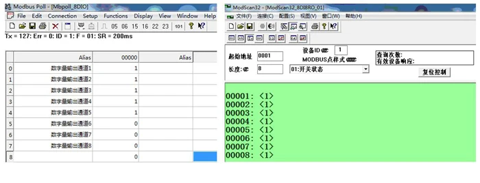
1. Output coil register (function code: 0x01H, 0x05H, 0x0FH)
|
address |
parameter |
length |
Read/write |
MIN |
MAX |
Description |
|
00001 |
DO1 |
1 |
Read/write |
0 |
1 |
Digital output bit 1 status |
|
00002 |
DO2 |
1 |
Read/write |
0 |
1 |
Digital output bit 2 status |
|
00003 |
DO3 |
1 |
Read/write |
0 |
1 |
Digital output bit 3 status |
|
00004 |
DO4 |
1 |
Read/write |
0 |
1 |
Digital output bit 4 status |
|
00005 |
DO5 |
1 |
Read/write |
0 |
1 |
Digital output bit 5 status |
|
00006 |
DO6 |
1 |
Read/write |
0 |
1 |
Digital output bit 6 status |
|
00007 |
DO7 |
1 |
Read/write |
0 |
1 |
Digital output bit 7 status |
|
00008 |
DO8 |
1 |
Read/write |
0 |
1 |
Digital output bit 8 status |
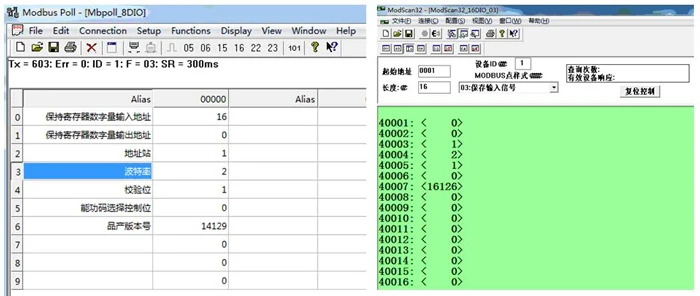
2. Holding registers (function codes: 0x03H, 0x06H, 0x10H)
|
address |
parameter |
length |
Read/write |
MIN |
MAX |
Description |
|
40001 |
DI (1~8) |
2 |
Read only |
0 |
0xff |
Read the status of an 8-bit digital input |
|
40002 |
DO (1~8) |
2 |
Read/write |
0 |
0xff |
Control the state of the 8-bit digital output |
|
40003 |
Device address |
2 |
Read/write |
1 |
247 |
1 (default) |
|
40004 |
Baud rate |
2 |
Read/write |
1 |
5 |
1 (4800) 2 (9600) default 3 (19200) 4 (38400) 5 (57600) |
|
40005 |
Check Digit |
2 |
Read/write |
1 |
3 |
1 (no parity.) default 2 (odd check) 3 (even parity) |
|
40006 |
Network protection time setting |
2 |
Read/write |
1 |
2000 |
If it is set to >=1800, the network protection function is cancelled, and the 0-1799S range is the network protection time. After this time, the DO output is reset. |
|
40007 |
product version |
2 |
Read only |
0 |
-- |
Year + month + day |
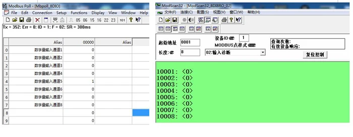
3. Discrete input register (function code: 0x02H)
|
address |
parameter |
length |
Read/write |
MIN |
MAX |
Description |
|
10001 |
DI1 |
1 |
Read only |
0 |
1 |
Digital input bit 1 status |
|
10002 |
DI2 |
1 |
Read only |
0 |
1 |
Digital input bit 2 status |
|
10003 |
DI3 |
1 |
Read only |
0 |
1 |
Digital input bit 3 status |
|
10004 |
DI4 |
1 |
Read only |
0 |
1 |
Digital input bit 4 status |
|
10005 |
DI5 |
1 |
Read only |
0 |
1 |
Digital input bit 5 status |
|
10006 |
DI6 |
1 |
Read only |
0 |
1 |
Digital input bit 6 status |
|
10007 |
DI7 |
1 |
Read only |
0 |
1 |
Status of digital input bit 7 |
|
10008 |
DI8 |
1 |
Read only |
0 |
1 |
Digital input bit 8 status |
Chapter III Product Configuration
One. Communication settings
1. Default factory communication parameters
|
project |
Register address |
Description |
Defaults |
|
address |
40003 |
1 (default) |
1 |
|
Baud rate |
40004 |
1 (4800) 2 (9600) default 3 (19200) 4 (38400) 5 (57600) |
2 |
|
Check Digit |
40005 |
1 (no parity.) default 2 (odd check) 3 (even parity) |
1 |
|
Data bit |
--- |
Not adjustable |
8 digits |
|
Stop bit |
--- |
Not adjustable |
1 person |
2. Reset communication parameters
1. In order to prevent the user from forgetting the set communication parameters, the module cannot communicate with the module. The recovery initialization function was deliberately designed.
2. Hold the "key" on the back of the module with the toothpick for more than 3 seconds, until the red light of the module "RUN" flashes and press and hold the button. The RUN light flashes 3 times and then returns to normal (running state). Factory settings. Then, after the module is powered off and the power is turned back on, the communication parameters have been reset to the default values.
Second, the communication indicator description
1. After the module is powered on, the red working indicator of the module “RUN” is always on. When the reset button is pressed, it will flash three times at 1 second intervals.
2. In the module communication, the communication indicator flashes according to the received data “RXD”, and the data “TXD” flashes regularly after the CPU processes. When the communication is not normal, the flashing status will flash abnormally to determine the cause of the communication failure.
Third, the host computer debugging instructions
This module provides a standard modbus debugging software to implement the function debugging and parameter setting of the module. Please follow the steps below:
l Connect the computer and module with RS485 converter
l Connect the 24V external power supply to the module and power it on. To avoid unnecessary damage, please check whether the positive and negative terminals of the power supply are connected correctly before powering on.
l Open the file edited by the debugging software, set the correct communication parameters, open the communication port, and enter the function debugging or parameter setting interface.
l Select the appropriate settings, acquisition and control options
Note: When wiring the module terminals, it is recommended to remove the terminal strips first, then plug them in again. And check according to the wiring diagram and the wiring symbol on the module, and then power on again after confirming the error.
Related Products

RFID AGV 125Khz EM4100 Card Reader Rs485 ModBus RTU for PLC


13.56Mhz RFID NFC IC Card Read Writer RS485 Modbus RTU For PLC

RS485 Modbus Temperature Controller digital Cold Storage Temperature Controller Thermostat


Modbus TCP to Modbus RTU Remote IO Module Data Acquisition isolated designed with Digital output M120T

