Description
RS485 electric lock control board; mainly used in smart storage cabinets, express cabinets, vending machines and other equipment to control the opening of electric locks; we can provide secondary development protocol documents; the control board can add more control boards through the cascade interface, Up to 31 control boards can be connected in series.
Product specifications
Working voltage: DC12V-24V
Communication method: RS458(If you need to connect the RS232 serial port or connect the USB interface; then you need to buy a converter)
Data format: using hexadecimal command data format as Hex
Serial port settings: baud rate 9600; data is 8; stop is 1; flow control is None
Output current: maximum 6A current
Control mode: default normally open output (can control power-on unlock type electric lock); if you need to control power-on atresia type electric lock; you can contact us to modify the control method.
Packing list
RS485 control board*1, power communication line*1, 1.6m electric lock cable
(RS232 converter and USB serial cable need to be purchased separately)
- Power and communication interface
- Control board cascade interface
- CH1-CH8 Electric lock connection port (terminal type: XH2.54)
- Fully open button
- Control board address setting switch
- TTL communication interface
1.+12V 2. GND 3. 485A(+) 4. 485GND 5. 485B(-)
- Positive output(+)、7.Negative output(-)、8. Feedback input、9. Feedback common
10.VCC、 11.RXD、 12.TXD、 13.GND
Connection method of RS485 communication signal cable and RS232 serial converter:
485A connection converter R+ interface
485B connection converter R- interface
The remaining interfaces do not need to be connected
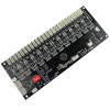
8-channel control board (can control 8 electric locks):
Input voltage: DC12V-24V
Output current: maximum output 6A
Communication method: RS485 communication/TTL communication
Size: 95*90mm
18-channel control board (can control 18 electric locks)
:
Input voltage: DC12V-24V
Output current: maximum output 6A
Communication method: RS485 communication/TTL communication
Size: 172*88mm
24-channel control board (can control 24 electric locks)
:
Input voltage: DC12V-24V
Output current: maximum output 6A
Communication method: RS485 communication/TTL communication
Size: 214*88mm
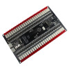
50-channel control board (can control 50 electric locks)
:
Input voltage: DC12V-24V
Output current: maximum output 6A
Communication method: RS485 communication/TTL communication
Size: 219*127mm
With LED light control interface, according to the different feedback signal of the door lock; it can support the function of lighting after unlocking or lighting after locking
RS485 control board communication protocol
(Applicable to the control board of 8 12 18 24 36 50 channels)
一、Hardware interface:
1.Communication method: RS485 communication, 1~99 devices can be connected on the same 485 bus.
2.Baud rate 9600; data bit 8; stop bit 1; flow control None.
3.The unlock command is hexadecimal; the data format is Hex.
4.Working voltage DC12~24V
4.Support up to 31 control boards in series.
5.Can control normally closed electric locks. (Control normally open electromagnetic locks need to be customized)
二、Control Commands:
- Full open command(Send this command to open all electric locks of a control panel)
|
Command header |
Board address |
Lock address |
Function code |
Check code /BCC |
|
8A |
01 |
00 |
11 |
9A |
For example, the host computer sends 8A 01 00 11 9A to the lock board of address 1 and after receiving this command, all the locks on the No. 1 board are opened at an interval of 300 milliseconds; until the last one.
- Unlock command:
|
Command header |
Board address |
Lock address |
Function code |
Check code /BCC |
|
8A |
01 |
01 |
11 |
9B |
- The board address is the address number set by the DIP switch on the lock board.
- Lock address is the number of the channel that needs to be unlocked.
- The unlock function code is fixed at 11
- For example, the host computer sends 8A 01 01 11 9B (hexadecimal) and returns the following data after 500 milliseconds.(The feedback data includes the board number, lock number and the current status of unlocking.)
The format of the feedback data is as follows:
|
Command header |
Board address |
Lock address |
Unlocked state 11/00 |
Check code /BCC |
|
8A |
01 |
01 |
00 |
8A |
- Note: The unlocking state is related to the lock. Locks are divided into door opening feedback type and door closing feedback type.
- Door closing feedback type: the door opening feedback status is 00, which means unlocking is successful; 11 means unlocking failed;
- Door opening feedback type: unlocking feedback 11 means unlocking is successful; 00 means unlocking failed
For example, a closed door feedback type electric lock will feedback the following data after unlocking:
- 8A 01 01 00 8A (indicating successful unlocking)
- 8A 01 01 11 9B (indicating unlock failure)
三、Query the status of the lock
1.Query the status of a single lock:
|
Command header |
Board address |
Lock address |
Function code |
Check code /BCC |
|
80 |
01 |
01 |
33 |
B3 |
- For example: the upper computer sends 80 01 01 33 B3 (hexadecimal) 200ms after the lock board will feedback the following data:
|
Command header |
Board address |
Lock address |
Feedback status 00/11 |
Check code /BCC |
|
80 |
01 |
01 |
33 |
B3 |
- Door open feedback type lock: query status feedback 11 means the lock status is open; 00 means the current lock status is closed.
- Closed door feedback type lock: query status feedback 00 indicates that the lock state is open; 11 indicates that the current lock state is closed.
- For example, the lock query status feedback of the closed door feedback type is in the following format:
80 01 01 00 80 (indicating that the lock is open)
80 01 01 11 91 (indicating that the lock is closed)
四、Query the status of all locks
In actual use, the user needs to know the status of all the locks of each cabinet, so it is possible to query all the lock statuses and query the status of all the locks on a lock board.
- Query command:
|
Command header |
Board address |
Fixed code |
Function code |
Check code /BCC |
|
80 |
01 |
00 |
33 |
B2 |
For example, the host computer sends 80 01 00 33 B2 (hexadecimal) to read the status of all electric locks on board 1
- After the query, the following data is returned:
|
Command header |
Board address |
State 1 |
State 2 |
State 3 |
Function code |
Check code /BCC |
|
80 |
01 |
CH 17-24 lock |
CH 9-16 lock |
CH 1-8 lock |
33 |
XX |
Taking the 24-channel lock board as an example, there are three byte states for feedback of all lock states.
- State 1 is the lock state of channels 17-24. 01 02 04 08 10 20 40 80represents the state of 8 locks。
- State 2 is the lock state of channels 9-16. 01 02 04 08 10 20 40 80 represents the state of 8 locks。
- State 3 is the lock state of channels 1-8. 01 02 04 08 10 20 40 80 represents the state of 8 locks
- For example, closed door feedback type lock: the data returned by the command to query all lock states is 80 01 01 01 01 33 B3, which means that the three locks 17, 9, and 1 of the lock plate are closed, and the rest of the locks are open.
- Note: The check code can be calculated by BCC check (exclusive OR check)
五、Multi-channel unlock command
|
Command header |
Board address |
State 1 |
State 2 |
State 3 |
Check code /BCC |
|
90 |
01 |
CH 1-8 lock |
CH 9-16 lock |
CH 17-24 lock |
XX |
- For example, the host computer sends 90 01 02 02 02 93 (hexadecimal), which means to open the 2, 10, 18 channel lock.
- Note: The check code can be calculated by BCC check (exclusive OR check)
六、The following functions need to be customized by contacting us
(the following functions are not included by default)
- Active feedback function:After the lock status changes, the data is actively uploaded to the host computer to feedback the opening or closing information.
The feedback data format is as follows:
|
Command header |
Board address |
Lock address |
Lock state |
Check code /BCC |
|
82 |
01 |
01 |
00/11 |
** |
For example: the No. 1 lock on the No. 1 board uses the lock with feedback of closing the door; the main upload after closing the lockThe data is 82 01 01 11 93; the status bit is 11; if the door open feedback lock is used, the status bit is 00 after the lock is closed.
- Long power-on function:
This function is suitable for controlling the magnetic lock that is unlocked after power off, that is, the magnetic lock will be locked after the magnetic force is generated by the continuous power on; the magnetic lock will be unlocked after the power is off.
- The host computer sends the following data to turn on the long power-on:
|
Command header |
Board address |
Lock address |
Function code |
Check code /BCC |
|
9A |
01 |
01 |
11 |
** |
For example, the host computer sends: 9A 01 01 11 8B; it represents the number 1 lock plate Channel 1 performs long power-on operation; and uploads the feedback status of the channel.
- The host computer sends the following data to turn off the long boot:
|
Command header |
Board address |
Lock address |
Function code |
Check code /BCC |
|
9B |
01 |
01 |
11 |
** |
For example, the host computer sends: 9B 01 01 11 8A; it represents the number 1 lock plate Channel 1 closes the long power-on operation; and uploads the feedback status of the channel.
七、Modify the communication baud rate (default baud rate is 9600)
The baud rate can be modified to: 9600, 19200, 38400, 57600, 115200
八、1~24 channel unlock commands corresponding to the 1st board
Full open command: 8A 01 00 11 9A
8A 01 01 11 9B Open channel 1 8A 01 02 11 98 Open channel 2
8A 01 03 11 99 Open channel 3 8A 01 04 11 9E Open channel 4
8A 01 05 11 9F Open channel 5 8A 01 06 11 9C Open channel 6
8A 01 07 11 9D Open channel 7 8A 01 08 11 92 Open channel 8
8A 01 09 11 93 Open channel 9 8A 01 0A 11 90 Open channel 10
8A 01 0B 11 91 Open channel 11 8A 01 0C 11 96 Open channel 12
8A 01 0D 11 97 Open channel 13 8A 01 0E 11 94 Open channel 14
8A 01 0F 11 95 Open channel 15 8A 01 10 11 8A Open channel 16
8A 01 11 11 8B Open channel 17 8A 01 12 11 88 Open channel 18
8A 01 13 11 89 Open channel 19 8A 01 14 11 8E Open channel 20
8A 01 15 11 8F Open channel 21 8A 01 16 11 8C Open channel 22
8A 01 17 11 8D Open channel 23 8A 01 18 11 82 Open channel 24
九、1~24 channel query lock status command corresponding to No. 1 board
Query all lock status commands:80 01 00 33 B2
80 01 01 33 B3 Query channel 1 80 01 02 33 B0 Query channel 2
80 01 03 33 B1 Query channel 3 80 01 04 33 B6 Query channel 4
80 01 05 33 B7 Query channel 5 80 01 06 33 B4 Query channel 6
80 01 07 33 B5 Query channel 7 80 01 08 33 BA Query channel 8
80 01 09 33 BB Query channel 9 80 01 0A 33 B8 Query channel 10
80 01 0B 33 B9 Query channel 11 80 01 0C 33 BE Query channel 12
80 01 0D 33 BF Query channel 13 80 01 0E 33 BC Query channel 14
80 01 0F 33 BD Query channel 15 80 01 10 33 A2 Query channel 16
80 01 11 33 A3 Query channel 17 80 01 12 33 A0 Query channel 18
80 01 13 33 A1 Query channel 19 80 01 14 33 A6 Query channel 20
80 01 15 33 A7 Query channel 21 80 01 16 33 A4 Query channel 22
80 01 17 33 A5 Query channel 23 80 01 18 33 AA Query channel 24
十、Address code switch setting
- No. 12345 switch respectively represents the number 1, 2, 4, 8, and 16; this number can be added together; you can set the address of the No. 1-31 board at most.
Verification method:
#include <stdio.h>
/*
Use online tools to calculate the value of 485 input
*/
unsigned char txbuff[6]={0x90,0x01,0x01,0x11,0x01,0x00};
unsigned char CRC_XOR(unsigned char *buff,unsigned char len)
{
unsigned char i;
unsigned char temp;
for(i=0; i<len; i++)
temp ^= buff[i];
return temp;
}
int main () {
unsigned char i,j;
for(i=0x00; i<0x19; i++)
{
txbuff[2] = i;
txbuff[5] = CRC_XOR(txbuff,5);
for(j=0; j<6; j++ )
{
if(txbuff[j]<0x10)
printf("0%x
",txbuff[j]);
else
printf("%x ",txbuff[j]);
}
printf("\n");
}
return 0;
}


