Description

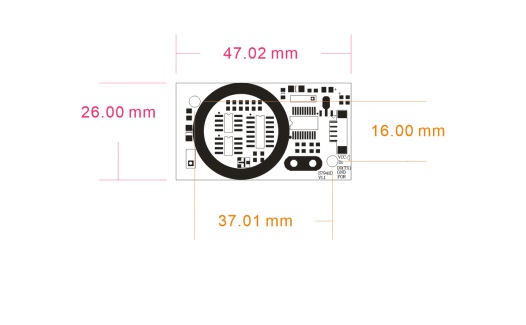
7941E card reader module, integrated high-performance card reader RF circuit and antenna, while supporting ID and 1C card, select wg26, Uart interface
Voltage DC12V
Current 40mA
Supports 125KHz (EM card) and 13,56MHz (ISO l4443A) cards
Volume 47mm* 26mm* 5mm (including antenna)
Working environment: -20 ° c-70 ° c
EM4100 reader distance> 8cm
IC card reader distance> 5cm
interface:
VCC Power supply
D1 wg data1
D0 wgdata2
GND
FOR wire GND indicates wg34
wg26 code
|
0 |
00111101 |
00010010 |
11010110 |
1 |
|
Parity check |
3D |
12 |
D6 |
Odd check |
|
0 |
01101011 |
00111101 |
00010010 |
11010110 |
0 |
|
Parity check |
6B |
3D |
12 |
D6 |
Odd check |
|
UART interface |
|
||||
|
Data head |
length |
Card type |
card number |
BCC calibration |
The number of ends |
|
0x02 |
0x09 |
0x01 |
SN0-SN3 |
(XOR of all data |
0x03 |
0x02 EM4100
0x01 MF1K
0x03 MF 4K
0x10 H ID card
0x11 T5567
0x20
0x21 IS014443B
0x22 FELICA
0x30 15693 tag
0x50 CPU card
0x51 sector information
OxFF keyboard data
The second byte, 0x0A, indicates that the entire data length is 10 bytes, including data start and end of data.
The fourth byte to the 8th byte 0x2E 0x00 0xB6 0xD7 0xB5 The five bytes represent the read number, where the fourth byte 0x2E is the hidden card number.
The 9th byte 0xF2 represents the BCC check for the second byte to the eighth byte.
The tenth byte 0x03 indicates that the data ends.
Precautions
1, please stay away from the interference source, strong interference signal may affect the reader.
2, the choice of linear power supply can significantly improve the reading distance and the effect of switching power supply on the reading distance has a certain attenuation. but
Does not affect the normal and stable work
3, the module 9 ~ 12V range can work properly, remember that you can not use a higher voltage
4, the block itself will occur high-frequency signal, the analog circuit may have some interference


