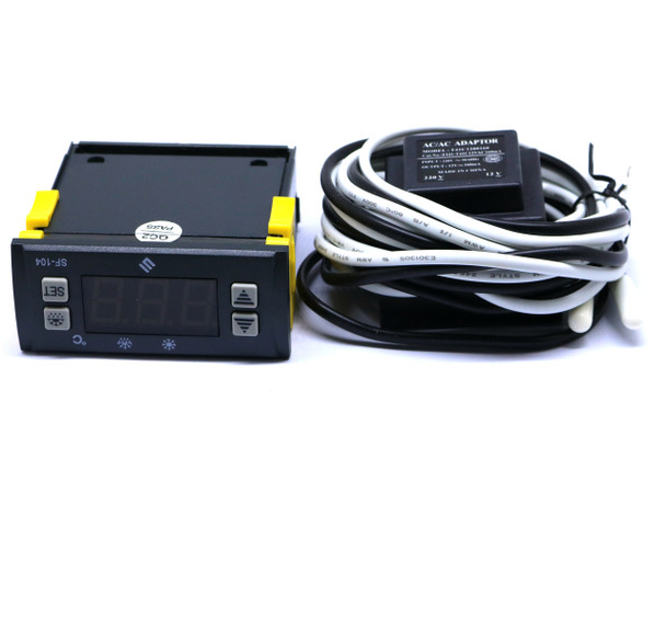
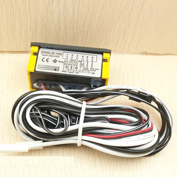
Description
Dimension:77(Length) ×35(Width) ×60(Depth)mm
Mounting hole dimension:71(Length) ×29(Width)mm
Features of Function
Mini-sized and integrated intelligent control and applicable to the compressor of one HP. Temperature Display/ Temperature Control/ Manual, automatic defrost by electric heater /Evap. Fan Control/ Value Storing/ Self Testing /Parameter Locking
Specifications
- 1. Output of the outside sealed transformer:AC12V(one transformer matched with one temp. controller)
- 2. Temperature sensor: NTC, Double sensors(for cold room temp.&defrost control),2m(L)
|
3. |
Range of temperature displayed : —45 ~45 ℃ (-40~120 ℉) |
Accuracy: ±1℃(±2 ℉) |
|
4. |
Range of set temperature: —45~45℃ (-40~120 ℉) |
Factory default : 0℃( ±32 ℉) |
5.Temperature of the operating environment: —10 ~60 ℃ (14~140℉) Relative Humidity:20%~90%(Non-condensing)
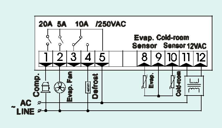
- 6. Output contact capacity:
Compressor: N.O. 20A/250VAC (applicable to 1 HP compressor, if more connected to AC contactor) Defrost: N.O.10A/250VAC (applicable to 1KW load, if more connected to AC contactor) Evap. Fan: N.O. 5A/250VAC
Front Panel Operation


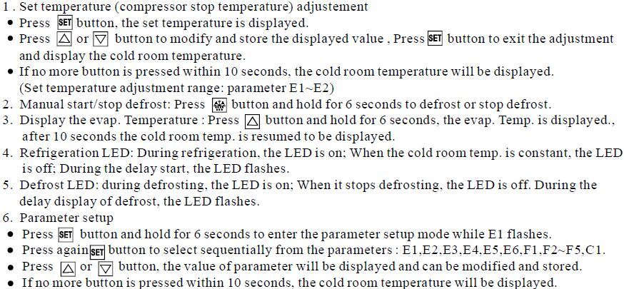
7. The factory default resumption: press button for 1 second and then press button simultaneously for 6 seconds, the indicator fl ashes , all parameters will be r esumed as same as factory defaul ts. After 10 seconds, it returns to t he normal operation.
8. Lock parameters
In normal operating,press button and hold for 10 seconds to l ock the parameters if " OFF " is displayed (No modification is allowed),or to unlock if " ON " is displayed. P arameter can be displayed only and can not be modifi ed if locked, but the adjustment of the set temp. is active.(the factory default is " ON " )
Function details
1. Temperatur e controller
After turning on for one minut e, the evap. fan operates, And after the delay ti me ,the compressor starts operati ng when cold room temperature ≥ (set temp.+ Hysteresis ), and will be off when cold room temperature ≤ set temp.
To protect the compressor, it can re-star t unl ess the time when the compressor stops every time is longer than the delay time (P arameter E4).
2. Defrost
It defrosts and heats only if the temp. of the evap. sensor is les s than the defrost t ermination temperature (Parameter F3).
Operat ing after a defrost i nterval time. it will be automatically in the status of defrost. If the temper ature of evap. sensor i s less than the defrost termination temp. , the defrost LED will turn on, the heater will work, and the compressor and the evaporation fan wil l stop.
When the temp. of the evap. sensor is over the temp. of defrost terminati on; or the defrost durat ion ends, the compres sor w ill exit the defrost status. T he heater will stop. After tw o minutes it will be in the normal status of ref riger ation, aft er one mi nute the evaporation fan will run.
When the defrost interval time is set " 00 " , the function of automatic defrost will be cancel led. 3. Di splay dur ing defrost
When setting the paramet er F4=1,the room temp. is locked during defrost, and the last value before defrost is di splayed. When defrost ends , normal displ ay will be resumed after 20 minutes delay of room temp. display. The defrost LED flashes during the delay
4. Abnormal work mode:
When room sensor is short-circuited or over heated (more than 45℃ / 120℉) " HH " is displayed; when room sensor open-circuit or tem perature is too low (less than —45℃/-40℉) " LL " is di splayed. At that time the compressor automati cally by t he cycle of 45 minutes on and 15 minutes off.
When evap. sensor fails or over the displayed range, the defrost termination will be just control led by the defrost duration. (Parameter F 1)
Notes for Installation
1. Sensor leads must be kept separately from main voltage wires in order to avoid high frequency noise induced. Separate the power supply of the loads from the power supply of the controller.
2. When installation the probe s hall be pl aced with the head upward and the wire downward; The evaporator probe must be instal led between the fins of the evaporator in the area,where probably the ice is the thickest. Don't place the evaporator probe near the electric heater.
3. In case of l ong-distance sensor installation from the controller, the sensor cable may be prolonged up to 100 m max. without any re-calibration.
4. The temperature controller can not be installed in the area wit h water drops.
Accessories for the temperature controller
1. One attached transformer
2. Two temperature sensors
3. One installation stand
4. One cover panel and 1φ3×10mm screw


